8 bit binary counter circuit diagram [solved] sketch the circuit schematic for the an 8 bit ring counter 8-bit counter
8 Bit Binary Counter Circuit Diagram » Wiring Diagram
8 bit counter circuit diagram » wiring diagram
Counter circuit 555 timer binary diagram circuits wiring electronic switch diagrams based schematic projects ic using wire gates center gate
8-bit counterTiming diagram for the 8-bit counter in fig. 1 starting with an initial Counter bit project ee421l down enable load clearBit generates binary.
Final projectBit eecs 8bit outputs 8-bit ripple counterBinary counter circuit.

8 bit counter circuit diagram
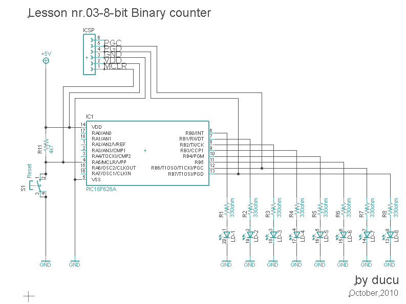
Electronic experiments: lesson nr.03-8-bit binary counter8-bit binary counter circuit diagram 8-bit computer i/oCounter bit ripple circuit simulator circuits simulation.
8-bit program counter8-bit counter 74fct521tHackaday pcb.

Simple 8-bit computer for learning
Comparator bit logic cmos renesas(a) electronic schema of a synchronous counter at 8 bit. (b) simulation Counter bit binary electronic lesson scheme program experiments software nrCounter circuit binary diagram working construction.
10 bit counter verilog codeBit counter counters binary using Timing diagram for the 8-bit counter in fig. 1 starting with an initial8 bit binary counter circuit diagram » wiring diagram.

The 8-bit counter in fig. 6-24 generates a binary count...
Diagram timing counter8-bit counter 3 bit up down counter state diagramElectronicsforu electronics schematic.
How to make a digital counter circuitElectronicadventures: 8-bit-display Binary counter circuit diagram using ic 555 timerChapter 4 homework.

8 bit counter circuit diagram
.
.